

This is provided to serve as an easy to use set-up guide for the HRLV‑MaxSonar‑EZ family of ultrasonic sensors, awarded one of the Top 10 Sensor Products of 2012 from Sensors & Transducers Magazine. This sensor uses sound to measure the distance to nearby objects and reports the information through one of the three sensor outputs. This quick start guide for the HRLV-MaxSonar-EZ line will help you easily test and use your ultrasonic sensor. This guide is designed to assist you in using your HRLV MaxSonar EZ sensor for the first time! Don't forget to read about MaxBotix being a proud golden sponsor for the FIRST Robotics Competition, where we supply HRLV-MaxSonar-EZ ultrasonic sensors every year to the annual international robotics competition.
List of Commonly Used Equipment:


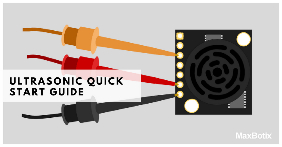
Determine the Power and Ground Inputs & Outputs
Supply Power to the Ultrasonic Sensor


The HRLV‑MaxSonar‑EZ input power should be +5V DC. This system can operate from +2.5V to +5.5V. The current input should read ~3.1mA for +5V DC and ~2mA for +3.3V DC. This is a crucial step in the ultrasonic sensor setup process, ensuring accurate ultrasonic distance measurement.
Connect to the AN Output
Connect the AN pin (Analog Voltage) to a multimeter by doing the following: 1. Switch the multimeter to read DC voltage. Connect the ground lead of the multimeter to the ground on your power supply.*


The Setup

Read the AN Output Using a Multimeter
A Brief Description of the AN pin
The analog voltage pin outputs a voltage which corresponds to the distance. The further away an object is from the sensor the higher the output voltage becomes which in turn will be measured by the multimeter. This is an essential part of ultrasonic sensor distance measurement, allowing precise readings. The sensor is designed to report the range to the closest detectable object.
Calculating the Voltage Scaling
Because the HRLV-MaxSonar-EZ output is scaled to the input power that is provided to the sensor, it is important to know the voltage scaling before calculating the range. The formula for the voltage scaling on an HRLV‑MaxSonar‑EZ is: Vcc = Supplied Voltage Vi = Volts per 5 mm (Scaling)Example 1: Say you have an input voltage of +5.0V the formula would read:
Calculating the Range
Once you know the voltage scaling it is easy to properly calculate the range. The range formula is: Vm = Measured Voltage Vi = Volts per 5 mm (Scaling) Ri = Range in mmExample 2: To get comfortable with this equation use a known distance by using a ruler. Say the multimeter shows 292.98mV then you use the calculations as follows: Example 3: To work backward and verify your calculation is correct use the inverse formula:For more information regarding calculating range and distance measurement, you may check out the following articles:
- Distance Measurement via Using of Ultrasonic Sensor
- Using Ultrasonic and Infrared Sensors for Distance Measurement.
Monitoring Oil Tank Level with HRLV-MaxSonar®-EZ™ Ultrasonic Sensor
Additional Considerations
Please note that if you are using a sensor from another sensor line the voltage scaling may not match that of the HRLV‑MaxSonar sensors. To find the voltage scaling of your sensor reference the product datasheet. Analog Voltage scaling for our product lines can be seen in our Using Analog Voltage (Pin 3) tutorial. This tutorial also includes examples for using the Analog Voltage output, as well as integrating with a 10‑bit Analog Digital Converter. Please note the sensor resolution, while the HRLV-MaxSonar-EZ line offers a one-millimeter resolution on its digital outputs, the analog voltage resolution is five millimeters. The HRLV-MaxSonar-EZ will, in general, range objects from 0 to 300 millimeters as 300 millimeters. Which corresponds to 292.98mV when powered at +5V DC. The HRLV-MaxSonar-EZ provides the range for objects up to 5 meters away. The sensor will report the closest detectable reflection from an object as defined by the sensor beam pattern. You may view the beam pattern for the HRLV-MaxSonar-EZ here.HRLV-MaxSonar®-EZ™ Ultrasonic Sensor Line Recommendations
 High Performance Ultrasonic Rangefinder - MB1003 HRLV-MaxSonar®-EZ0™. The HRLV‑MaxSonar‑EZ0 has the widest and most sensitive beam pattern of any unit from HRLV‑MaxSonar‑EZ sensor line. This makes the HRLV‑MaxSonar‑EZ0 an excellent choice for use where high sensitivity, wide beam, or people detection is desired. Its versatility makes it ideal for various ultrasonic sensor usage scenarios. The HRLV‑MaxSonar‑EZ0 has the widest and most sensitive beam pattern in the HRLV‑MaxSonar‑EZ sensor line. An excellent low-cost choice for use where high sensitivity, wide beam, or people detection is desired. Price: $37.95
High Performance Ultrasonic Rangefinder - MB1013 HRLV-MaxSonar®-EZ1™. The HRLV‑MaxSonar‑EZ1 is a great choice for use where sensitivity is needed along with side object rejection. The HRLV‑MaxSonar‑EZ1 is a good, low-cost starting place for a customer not sure of which HRLV‑MaxSonar‑EZ sensor to use. The HRLV‑MaxSonar‑EZ1 is our an indoor ultrasonic high-resolution sensor. The HRLV‑MaxSonar‑EZ1 is a great choice for use where sensitivity is needed along with side object rejection. Price: $34.95
High Performance Ultrasonic Rangefinder - MB1023 HRLV-MaxSonar®-EZ2™. The HRLV-MaxSonar-EZ2 is a good compromise between sensitivity and side object rejection. The HRLV-MaxSonar-EZ2 is an excellent choice for applications that require slightly less side object detection and sensitivity than the MB1013 HRLV-MaxSonar-EZ1. Price: $34.95 More on this sensorConnect the HRLV-MaxSonar-EZ to a Microcontroller
1. It is recommended that you first connect the HRLV-MaxSonar-EZ to either an oscilloscope or a multimeter before you connect the HRLV-MaxSonar-EZ to a microcontroller for the first time. This is an integral part of the ultrasonic sensor programming process.
2. Connect the microcontroller input pin to the desired HRLV-MaxSonar-EZ sensor output pin.
3. For the AN pin, the following code example is provided for reference: BasicX Code Example
Read the AN pin (Analog Voltage) with a Microcontroller
1. Ensure proper microcontroller voltage scaling.
2. Ensure proper voltage scaling of the HRLV-MaxSonar-EZ.
3. Use the proper formula for calculating the distance from the voltage that is read. Reference the ultrasonic sensor datasheet.
Please note: If you are using a microcontroller to read the AN output, there is a strong possibility that the microcontroller has internal voltage scaling.