


2021 First Robotics Teams - Welcome!
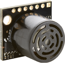 FRC competitors, once again we are supporting your work in the field of robotics by giving each team a free MB1043 MaxSonar Sensor from our HRLV-MaxSonar-EZ line. This small and lightweight sensor is designed for easy integration into your project, and it is a great option for autonomous robot navigation. Take a look at our data sheet for more information on your sensor’s specs!
How Ultrasonics work
All of our ultrasonic rangefinders will measure distance by tracking the time-of-flight of a sound wave. The diagram below shows how the sensor sends and receives the sound waves. Once the sensor emits a sound wave, it tracks how long it takes for the sound to reflect off of a surface and travel back to the sensor. The sensor then uses the known speed-of-sound to turn the time-of-flight into a range reading.
Using Your Ultrasonic Sensor with your NI roboRIO
Hook Up One Sensor To Your ROBORIO
Our sensors can easily be connected and powered by the analog inputs on your NI roboRIO. Do note that if you choose to use multiple sensors you will have to connect the trigger pin of the sensor to a digital output on the NI roboRIO. It is recommended to do multitasking such as creating a new thread to trigger the sensor while your main robot code is still running.
You will need to wire up 3 pins in order to use our sensors. Firstly, we need 5 Volt power (Pin 6) and Ground (Pin 7) to power the sensor. Secondly, we need to connect the Analog Output (Pin 3) so that we can read values from the sensor. To identify which pins these are on your sensor, you can note that one of the 7 pins on the sensor has a square copper pad around it, instead of a circular one. The square pad is Pin 1, and they count up along the board. The pins are also labeled on the back of the Circuit Board. We need to connect these pins to an Analog Input port on your RoboRIO. We will use Analog Port 0 in our example. Pin 6 on our sensor should be connected to the RoboRIO pin labeled “5V”, Pin 7 should be connected to the pin labeled with the Ground Symbol. Pin 3 should be connected to the pin labeled “S”. That's all we need to do to connect our Sensor to the RoboRIO. We've included a wiring diagram below.Single Sensor Setup 
Programming for use with a single sensor
Our sensors communicate with your RoboRIO using one of three methods: Analog Voltage Output (Pin 3), Pulse Width Output (Pin 2), or 5 Volt RS-232 Serial Output (Pin 5). In this example we are using Analog Voltage Output for simplicity. When power is applied to Pins 6 and 7 of our sensor, the voltage on pin 3 will change according to the distance between the sensor and the object in front of it. So in order to read this distance, we need the RoboRIO to measure the voltage on Pin 3. This can be done using the WPILib AnalogInput Library. First, let's import the library:Java: import edu.wpi.first.wpilibj.AnalogInput; C++: #includeNext, let's create an instance of the AnalogInput class and specify that it should use Analog Pin 0:
Java: private final AnalogInput ultrasonic = new AnalogInput(0); C++: frc::AnalogInput ultrasonic{0};Now that our sensor is setup, let's grab a distance value from the sensor:
Java: double rawValue = ultrasonic.getValue() C++: double rawValue = ultrasonic.GetValue()This will return a number in between 0 and 4095. 0 represents 0V applied, and 4095 represents 5V applied. Now that we know what voltage the sensor is outputing, let's scale this to our distance range:
Java: //voltage_scale_factor allows us to compensate for differences in supply voltage. double voltage_scale_factor = 5/RobotController.getVoltage5V(); double currentDistanceCentimeters = raw_value * voltage_scale_factor * 0.125; double currentDistanceInches = raw_value * voltage_scale_factor * 0.0492; C++: //voltage_scale_factor allows us to compensate for differences in supply voltage. double voltage_scale_factor = 5/RobotController.getVoltage5V(); double currentDistanceCentimeters = raw_value * voltage_scale_factor * 0.125; double currentDistanceInches = raw_value * voltage_scale_factor * 0.0492;This will return our distance in Centimeters or Inches. The Maximum range of our MB1043 sensor is 5 Meters, and the minimum range is 30 centimeters. For a detailed description of how this math is determined, please see our MB1043 datasheet. A complete example that takes readings from one sensor during the Autonomous period, and a different sensor during the Teleoperated period and publishes both to SmartDashboard can be found in robot.java and robot.cpp. Programming for use with multiple sensors Using multiple ultrasonic sensors requires a little more work, as the sensors may interfere with each others readings. To resolve this, MB1043 MaxSonar sensors are equipped with a Ranging Start/Stop pin. (Pin 4) If this pin is held high or left disconnected, the sensor will continuously free run. If we instead hold this pin low, we can force the sensor to stop ranging. By taking advantage of the Ranging Start/Stop pin and a Digital Output on the RoboRIO, we can trigger one sensor at a time therefore avoiding problems with multiple sensors interfering with each other. We can control the Ranging Start/Stop pin using the WPILIB DigitalOutput Library.
Multiple Sensor Setup

Java: public DigitalOutput ultrasonic_trigger_pin = new DigitalOutput(0); // Digital Pin 0 ultrasonic_trigger_pin.set(1) // Turn on the sensor. 0 for off. C++: frc::DigitalOutput ultrasonic_trigger_pin{0}; // Digital Pin 0 ultrasonic_trigger_pin.set(1); //Turn on the sensor. 0 for off.We can then read the values from each sensor using a separate Analog pin for each sensor, just as in Section 2. Do note that it takes approximately 100 Milliseconds for each sensor to complete a range reading. Therefore, we have to wait at least that long after turning the sensor on to receive updated range information. For more information on the timing of the MB1043, please reference our datasheet. A complete example that takes readings from one sensor during the Autonomous period, and a different sensor during the Teleoperated period and publishes both to SmartDashboard can be found in robot.java and robot.cpp. Users with more experience in programming/timing might also find the following diagram helpful, which allows multiple sensors to be chained together such that only one digital pin is needed to cause all the sensors to range one after the other.
 How this helps you Once you have your ultrasonic sensor hooked up, you can write code to control your Robot. For example, your robot could use these values to drive a certain distance in Autonomous. You could use range information to automatically perform an action when you approach a target. You could also use this data to assist your drivers during the Teleoperated period. Even if you are using other sensors, Ultrasonic sensors are a great addition. Only ultrasonic sensors can reliably detect certain surfaces such as glass. Transparency and color of objects have no effect on an ultrasonic sensor's ability to see an object. This is especially useful if you don’t know what kind of environment your robot will be operating in. If you need any help using our sensors or want to contact us for any other reason, you can reach us by email at techsupport@maxbotix.com or call 218-454-7363. Feedback is appreciated! If you'd like to purchase additional sensors, visit us at www.maxbotix.com, or contact us at sales@maxbotix.com. Thank you, and Have a great season! Additional Resources:
Download .Cpp Sample Code Download .Java Sample Code