
How to Calculate Distance from the Pin 3
The Analog Voltage pin on the MaxSonar family of sensors has been the most popular output for our users. All of the MaxSonar sensors have this output included. This guide will give a look into how to use it for obtaining the distance to the target being detected. The Analog Voltage output is scaled on all sensors to the power input of the sensor. The Analog Voltage output will output a linear voltage that gets larger as a target increases in distance from the sensor. This scaling will be outlined with each sensor family. For all examples the power input is +5VDC.Our standard LV-MaxSonar and XL-MaxSonar sensors assume the temperature is 22.5 degrees celsius. These sensors do not apply temperature compensation as the air temperature changes. Our HR‑MaxSonar sensors do apply automatic temperature compensation as the air temperature changes. To apply temperature compensation to your part please see the Temperature Compensation PDF here
LV-MaxSonar Sensors
This is for the LV-MaxSonar-EZ, LV-MaxSonar-WR, and LV-MaxSonar-WRC. All of our LV-MaxSonar sensors range to targets in inches. The formula for the voltage scaling on an LV-MaxSonar sensor family is: Vcc = Supplied Voltage Vi = Volts per inch (Scaling) Example 1
Calculating the Range
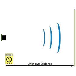
Once you know the voltage scaling it is easy to properly calculate the range. The range formula is: Vm = Measured Voltage Vi = Volts per Inch (Scaling) Ri = Range in inches Example 2: If your multimeter shows a measurement 292.98mV then you use the calculations as follows: Example 3: To work backward and verify your calculation is correct use the inverse formula:
Using an LV-MaxSonar with an ADC (Analog Digital Converter)
When using an LV-MaxSonar with an ADC, verify that the sensor and micro-controller are referencing the same power supply and ground. This also assumes that the ADC being used is perfectly accurate. When reading the sensor's output with the scaling in inches with a 10-bit ADC, divide the ADC output by 2 for the range in inches. If the ADC output reads 508 (maximum output) the range in inches is 254 inches. If the ADC output reads 250 the range in inches is 125 inches.
Standard XL-MaxSonar Sensors
This is for the XL MaxSonar EZ, XL-MaxSonar-AE, XL MaxSonar WR, and XL MaxSonar WRC. This formula does not include scaling for our 10 meter sensors: XL-MaxSonar-WRL1/WRLA1, XL-MaxSonar-EZL0/AEL0, and XL-MaxSonar-EZL1/AEL1. The voltage scaling formula for the standard XL MaxSonar sensor family is: Vcc = Supplied Voltage Vcm = Volts per cm (Scaling) Example 1: The formula should read:
Calculating the Range
Once you know the voltage scaling you can properly calculate the range. The range formula is: Vm = Measured Voltage Vcm = Volts per cm (Scaling) Rcm = Range in cm Example 2: If the multimeter shows a reading of 439.47mV, then you use the calculation as follows: in this case the range is 90cm Example 3: To work backward and verify your calculation is correct use the inverse formula:
Using a Standard Range XL-MaxSonar with an ADC (Analog Digital Converter)
When using a standard XL-MaxSonar with an ADC, verify that the sensor and micro-controller are referencing the same power supply and ground. This also assumes that the ADC being used is perfectly accurate. When reading the sensor's output with the scaling in centimeters with a 10-bit ADC, the range can be read directly off the ADC. If the ADC output reads 700 the range in centimeters is 700 centimeters. If the ADC output reads 200 the range in centimeters is 200 centimeters.
XL-MaxSonar Long Range Sensors
For the 10meter long range sensors the calculation formula is Vcc = Supplied Voltage V2cm = V per every 2 cm Due to a limitation of hardware the Analog Voltage output steps in 2cm increments. The formula to find the final distance is x 2= cm Vm = Volts measured V2cm = V per every 2 cm U = half measurement Example 1: Your multimeter has a reading of 439.47mV. x 2 = 180cm Example 2: To work backwards and verify correct calculation us the following formula =Vm If you input the calculated range from Example 1 of 180cm into the formula, your reverse formula should read =439.47mv
Using a Long Range XL-MaxSonar with an ADC (Analog Digital Converter)
When using a standard XL-MaxSonar with an ADC, verify that the sensor and micro-controller are referencing the same power supply and ground. This also assumes that the ADC being used is perfectly accurate. When reading the sensor's output with the scaling in centimeters with a 10-bit ADC, the range output has a 2cm resolution. If the ADC output reads 500 the range in centimeters is 1000 centimeters. If the ADC output reads 200 the range in centimeters is 400 centimeters.
5-Meter HR-MaxSonar sensors
This is our newest line of sensors. To calculate the distance using voltage please use the following formula (Vcc/1024)=V5mm Vcc = supplied voltage V5mm = Volts per 5mm Due to a limitation within the hardware of the sensor the Analog Voltage steps in 5‑mm increments. Example 1 (5/1024)=V5mm or 0.004885V (4.883mV) per 5 mm After the voltage scaling has been found, range calculation is now able to be done. To calculate range use the formula: (Vm/V5mm)x5=Rmm Vm = Volts Measured V5mm = Volts per 5 mm Rmm = Range in mm Example 2 The multimeter being used shows a voltage of 2.441V (2441.4mV). To find the distance the formula would look like (2441.4/4.883)x5=Rmm For this example the Range in millimeters is 2500 millimeters Example 3 To verify this is correct use the following formula: (Rmm/5) X V5mm)=Vm So the reverse calculation would look like: (2500/5)X 0.004883=Vm After calculation the Vm should read 2441.4mV or 2.441V
Using a 5-Meter HR-MaxSonar with an ADC (Analog Digital Converter)
When using a 5-meter HR-MaxSonar with an ADC, verify that the sensor and micro-controller are referencing the same power supply and ground. This also assumes that the ADC being used is perfectly accurate. Using a 10bit analog to digital convertor, one can read the analog voltage bits (i.e. 0 to 1024) directly and just multiply the number of bits in the value by 5 to yield the range in mm. For example, 60 bits corresponds to 300-mm (where 60 * 5 = 300), and 1000 bits corresponds to 5000-mm (where 1000 * 5 = 5000-mm).
10-Meter HR-MaxSonar sensors
This is our newest line of sensors. To calculate the distance using voltage please use the following formula (Vcc/1024)=V10mm Vcc = supplied voltage V10mm = Volts per 10mm Example 1 (5/1024)=V10mm = 0.004883 in this case V10mm will be 0.004883V or 4.883mV. After the voltage scaling has been found, range calculation is now able to be done. To calculate range use the formula: (Vm/V10mm)x10=Rmm Vm = Volts Measured V10mm = Volts per 10 mm Rmm = Range in mm Example 2 The multimeter being used shows a voltage of 1.2207V (1220.7mV). To find the distance the formula would look like (1220.7/4.883)x10=Rmm For this example the Range in millimeters is 2500 millimeters Example 3 To verify this is correct use the following formula: (Rmm/10) X V10mm)=Vm So the reverse calculation would look like: (2500/10)X 0.004883=Vm After calculation the Vm should read 1220.7mV or 1.2207V
Using a 10-Meter HR-MaxSonar with an ADC (Analog Digital Converter)
When using a 10-meter HR-MaxSonar with an ADC, verify that the sensor and micro-controller are referencing the same power supply and ground. This also assumes that the ADC being used is perfectly accurate. Using a 10bit analog to digital convertor, one can read the analog voltage bits (i.e. 0 to 1024) directly and just multiply the number of bits in the value by 10 to yield the range in mm. For example, 30 bits corresponds to 300-mm (where 30 * 10 = 300), and 1000 bits corresponds to 10,000-mm (where 1000 * 1 = 10,000-mm).