Key Takeaways
- A faulty power supply can lead to improper sensor operation
- Issues with a power supply will manifest throughout the entire circuit
- The power supply should be tested early in the troubleshooting process
Required Equipment
- Properly calibrated voltmeters and current meters
(resolution should be 10 times the parameter being measured)
- Oscilloscope with bandwidth up to 20MHz
- Sufficient input power source
- Programmable adjustable load
Whether you believe your power supply may be faulty or you are doing routine testing, it is important to verify the performance. Issues with a power supply can limit the performance of your equipment, and it even has the potential to damage your fine electronics. Proper and regular power supply testing can help minimize this risk.
Input Power
The power provided by your power supply is the key factor, but the first parameter to test is the voltage and current on the input side of your power supply. Verify the input power supply falls in the operating range for your power supply as listed in the specification or datasheet. Just like our sensors, improper input voltage to a power supply hinders proper operation whether you are using an AC/DC or a DC/DC power supply.
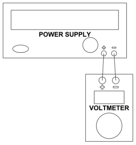
Output Voltage Accuracy
The LED display (when applicable) on your power supply may read 5.00VDC, but this may not always be accurate. Checking the accuracy of the output voltage with a properly calibrated voltmeter is a great way to verify this output voltage. Strictly speaking, you only need to verify that the output voltage is stable and within the operating range of your device. However, you may wish to continue to calculate the output voltage accuracy.
Test Setup
Test Procedure
- Set the input voltage to the nominal requirement for your power supply.
- Set the output voltage load to its maximum rated value.
- Measure the output voltage (VOUT) with the calibrated voltmeter.
- The output voltage accuracy can be calculated using the following formula

Note that DC/DC power supplies typically have a set output voltage where AC/DC have a variable output voltage. This displayed or set output voltage is (VNOM).
Noise & Output Ripple
Our sensors operate at peak performance when they receive smooth and clean voltage with minimum noise and output ripple. Output ripple and noise are also known as Periodic And Random Deviation (PARD). When there is noise on the voltage entering the part, it gets added to the amount of noise the part sees.
Specifically, output ripple and noise can be split into separate factors. Noise is a set of random high or low frequency spikes to the power supply. Noise is best mitigated by shielding the wires and operating as far from electrical noise sources as possible. Output ripple is periodic where noise is random. Output ripple is a periodic shift visible in the output voltage. This ripple is often generated by the periodic nature of AC power.
Viewing the power supply with an oscilloscope is required to view both output ripple and noise. Excess ripple or noise outside of a window that you would typically see in a controlled environment will degrade sensor performance. When testing the noise and output ripple the bandwidth should be sufficient to capture the full cycle of any output ripple.
Additional noise can be picked up on the oscilloscope probe itself. Using the shortest probe to ground length possible minimizes the amount of noise the probe receives. Take care to minimize any error and noise that you may add to the system.
Test Setup

Line Regulation
When there is a ripple or instability to the input voltage, it affects the output voltage. Line regulation specification indicates how much a change in output voltage you can expect due to a change in input voltage. The specification is typically presented as the change from minimum to maximum operating input voltage. Testing the line regulation may not be feasible if you are using an AC/DC power supply.
Test Setup

Test Procedure
- Set the input voltage to the nominal requirement for your power supply
- Measure the output voltage (VOUTNUM)using the calibrated voltmeter
- Set the input voltage to the maximum operating voltage of the power supply
- Measure the output voltage (VOUTMIN)using the calibrated voltmeter
- Set the input voltage to the minimum operating voltage of the power supply
- Measure the output voltage (VOUTMAX)using the calibrated voltmeter
- Find (VDEV), the maximum deviation from (VOUTNUM)
(VDEV) is the maximum of |VOUTNUM - VOUTMIN| or |VOUTNUM - VOUTMAX|
- Line regulation can be calculated using the following formula

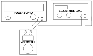
Load Regulation
The system being powered by the sensor will draw current from the power supply. The voltage will be affected by the total current drawn. On the DC output we can review Ohm's Law to see that V=IR. If we instantly increase the resistance of the circuit, the voltage will shift. Load regulation works to minimize any shifts due to a change in the loading of the circuit.
An output load change, a change in the resistance of the circuit, in terms of percentage of the max load should also be mentioned. The load regulation should be tested to these values.
Test Setup
Test Procedure
- Set the input voltage to the nominal requirement for your power supply
- Apply the maximum rated load, resistance, to the power supply
- Measure the output voltage at max load (VOUTML)using the calibrated voltmeter
- Set the load to the specified level for load regulation
- Measure the output voltage at the new load (VOUTNL)using the calibrated voltmeter
- Load regulation can be calculated using the following formula

Transient Recovery Time
Load regulation allows a power supply to adjust itself to continue providing the proper voltage after a change in load, but this adjustment doesn't happen instantaneously. The amount of time required for the voltage to return to the proper level (within an error band) is the transient recovery time.
The transient recovery time will be rated between two levels of the rated load. Please check your power supply datasheet to find the rated levels. As an additional note, the transient recovery time is measured from the moment that the load is changed until the voltage returns within the error band.
Test Setup

Test Procedure
- Set the input voltage to the nominal requirement for your power supply
- Locate the step load change specified for the power supply
- Program your adjustable load stepper according to the previous step
- Externally trigger your oscilloscope and switch the load over the specified range
- Measure the transient recovery time on your oscilloscope
Efficiency
Efficiency is a ratio that relates the total output power to the input power. While efficiency will exist for both AC/DC and DC/DC power supplies, it may not be feasible for all users to measure the efficiency of an AC/DC power supply.
Test Setup

Test Procedure
- Set the input voltage to the nominal requirement for your power supply
- Apply the maximum rated load to the power supply
- Measure the current (IIN) and voltage (VIN) to the power supply as well as the current (IOUT) and the voltage (VOUT) of the power supply
- Calculate the efficiency with the following equation

Locating Persistent Issues
You may continue to have issues after verifying all of the outlined issues in this article. If this is the case, you may wish to retest Output Voltage Accuracy at the pins of the sensor. Voltage droop can happen when running power through circuity. Additionally, circuits with more than one ground reference may have issues with ground loops. The power supply may be outputting a steady 5VDC, but these issues may create a droop or spike in the voltage at the point of the sensor. Testing at the pins of the sensor will help isolate this issue.
When testing
Noise and Output Ripple, we minimize the length of wire runs to minimize the amount of additional noise that is picked up. When power runs through the circuit, it will pick up additional noise. This means it is also a good idea to check for
Noise and Output Ripple directly at the sensor's pins to isolate this issue as well.
Not all problems are caused directly by the power supply, but testing your power supply is a great place to start. As it can be viewed as the beginning of any circuit, any problems with the power supply will continue to appear throughout the circuit.
Contact our technical support team if you are still having problems with your power supply. We are here to help you succeed.
Products Related to the Article

A USB ultrasonic proximity sensor with a True/False output. Designed for various installations: drive...
Buy Now

The XL-MaxSonar-WR is our most popular weather resistant sensor designed for outdoor detection and ranging...
Buy Now

The weather resistant HRXL-MaxSonar-WR is a rugged, ultrasonic sensor component module...
Buy Now
Articles Related to the Article Above
This is provided to serve as an easy to use set-up guide for the HRLV‑MaxSonar‑EZ family of ultrasonic sensors, awarded one of the Top 10 Sensor Products of 2012 from Sensors & Transducers Magazine. This ultrasonic sensor uses sound to measure the distance to nearby objects, and then reports the information through one of the three sensor outputs.
Read Full Article
Our sensors are improved to not allow unstable readings. Occasionally unstable range readings occur. Within this tutorial we will explain how to identify, troubleshoot, and eliminate the cause of unstable range readings. This will work for all sensor lines.
Read Full Article
When it comes down to it, you purchase a rangefinder for the range readings. The success of an application may hinge upon knowing the exact location of a target. However, a sensor may report one meter even if the target is not exactly one meter away from the sensor. Sensor specifications, such as resolution, precision, and accuracy, help us understand what wiggle room and error will be present in a reading.
Read Full Article


