Arduino
MaxBotix sensors have several outputs that can be interfaced with an Arduino Uno. Examples are shown below. In these examples, we will use an Arduino Uno R4. This process will be very similar on the Uno R3, as well as most other microcontrollers programmed in Arduino IDE.
Most MaxBotix inc. sensors including an Analog Voltage output. In this example we will use an MB1200 as it is representative of most sensors. Analog voltage is the simplest method for reading the output of the sensor. It does have one significant draw back compared to digital outputs, in that it has significantly less tolerance to noise. It is best suited to environments with short wires, and no significant noise sources (such as motors) nearby.
Three pins are needed to operate a sensor with this output: Power, Ground, and AV. The other 4 pins can be left not connected. Different models of sensor output range with a different scale factor between voltage and range. They are displayed in the table below.

| Sensor Family | Scale Factor |
|---|---|
| 7.65 Meter XL-EZ | Vcc/1024 per cm |
| 10 Meter XL-EZ | Vcc/1024 per 2cm |
| LV-EZ | Vcc/512 per Inch |
| 5 Meter TankSensors | Vcc/1024 per cm |
| 16.5 Meter TankSensors | Vcc/1024 per 2cm |
| 5 Meter HRXL | Vcc/1024 per 5mm |
| 1.5 and 10 Meter HRXL | Vcc/1024 per 10mm |
| IRXL | Vcc/1024 per 2cm |
| HRLV | Vcc/1024 per 5mm |
| 7.65 Meter XLWR | Vcc/1024 per cm |
| 10 Meter XLWR | Vcc/1024 per 2cm |
| CarSonar | Vcc/1024 per cm |
| HRLV-ShortRange | ((Vcc/1024)-300) per 6mm |
Most MaxBotix inc. sensors including a Pulse Width output. In this example we will use an MB1200 as it is representative of most sensors. Pulse Width outputs the range reading from the sensor by sending a Pulse and adjusting the amount of time that the pulse remains high.
Three pins are needed to operate a sensor with this output: Power, Ground, and PW. The other 4 pins can be left not connected. Different models of sensor output range with a different scale factor between pulse width and range. They are displayed in the table below.

| Sensor Family | Scale Factor |
|---|---|
| 7.65 Meter XL-EZ | 58uS/cm |
| 10 Meter XL-EZ | 58uS/cm |
| LV-EZ | 147uS/Inch |
| 5 Meter HRXL | 1uS/mm |
| 1.5 and 10 Meter HRXL | 1uS/mm |
| IRXL | 1uS/cm |
| HRLV | 1uS/mm |
| 7.65 Meter XLWR | 58uS/cm |
| 10 Meter XLWR | 58uS/cm |
| HRLV-ShortRange | 1uS/mm |
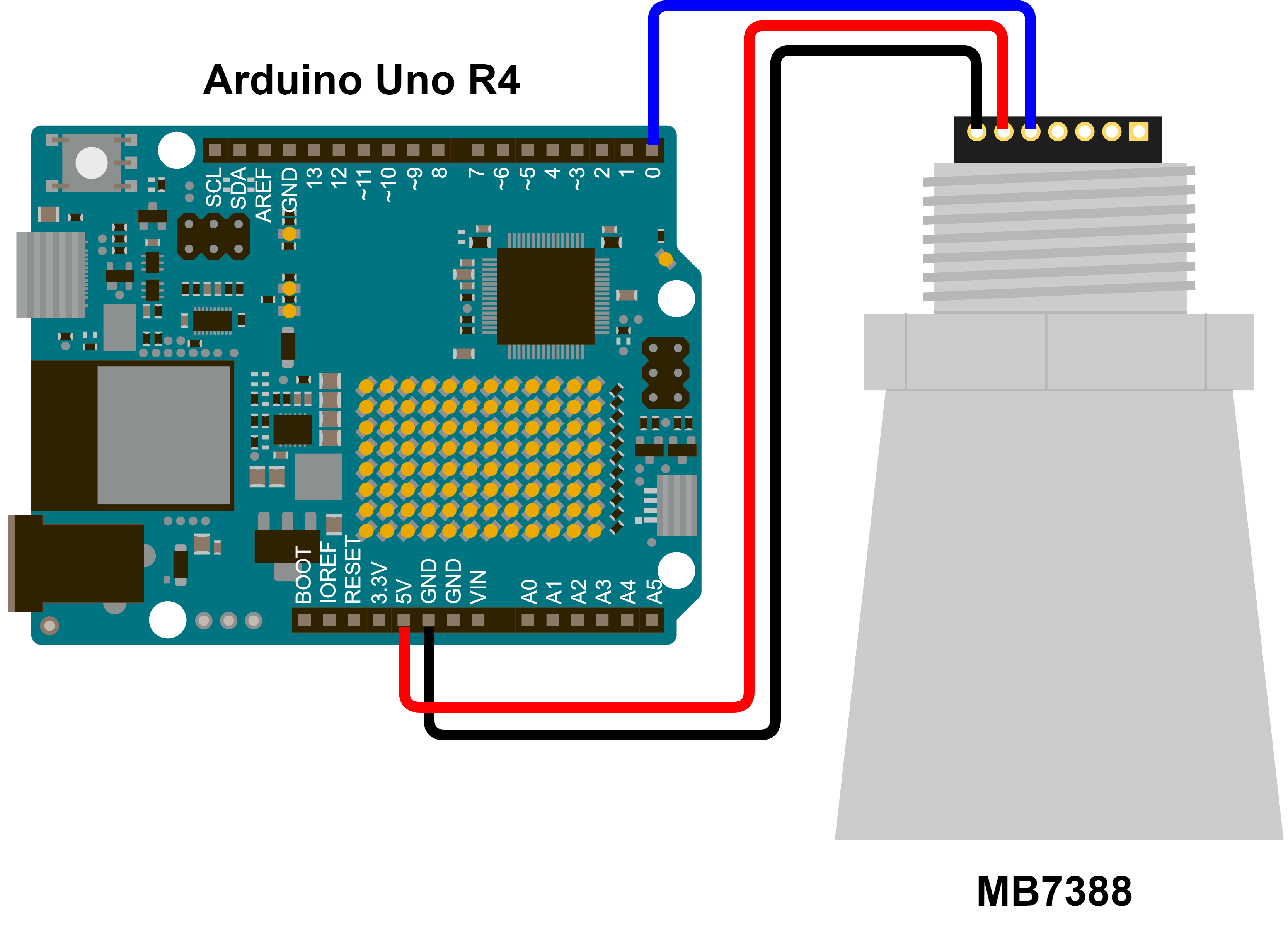
Most MaxBotix Inc. sensors include a serial output. That output comes in one of two varieties: RS-232 and TTL. Arduino (and most microcontrollers/Single Board Computers) communicate using TTL by default. RS-232 is useful because this is the protocol that standard serial ports on computers use. The difference between these two protocols is the polarity of the data. In TTL the data is idle HIGH, while in RS-232 the data is idle LOW. Some sensors come equipped with an RS-232 output and some with a TTL output. For use with an Arduino, the TTL outputs are much more convenient. In this example we will use an MB7388 as it is representative of most TTL sensors.
Three pins are needed to operate a sensor with this output: Power, Ground, and TX. The other 4 pins can be left not connected. Different models of sensor output range with a different scale factor between pulse width and range. They are displayed in the table below.


While TTL parts are prefered for use with Arduinos due to the simplicity, it is possible to use an RS-232 part with an Arduino. If this is desired, there are two options available. firstly, you could invert the RS-232 serial data externally to the Arduino. This can be accomplished using a transistor. secondly, you could use a software serial implementation which allows the RX line to inverted.
Many MaxBotix Inc. sensors include an Analog Envelope output. This is an advanced output requiring significant processing to be done. In this example we will use an MB1300 as it is representative of most AE capable sensors. Analog Envelope outputs the acoustic waveform with no digital processing applied. This allows you to process the waveform yourself and perform custom target detection algorithms. We will not discuss processing the incoming waveform data as that is highly specific to the application, and only focus on capturing that data.
Three pins are needed to operate a sensor with this output: Power, Ground, and AE. The other 4 pins can be left not connected. If desired, the RX pin can also be pulled to ground, which will allow the sensor to operate receive only, where it will show incoming signals on the waveform but never transmit. This is useful for some custom configurations.


