This document is created to assist you in your sensor selection, troubleshooting, and other services related to our products. We want to help you better understand our naming conventions, products exclusive to us, and industry terms.
1. Explaining our naming conventions
The letters used in our product names are abbreviations for characteristics the sensor has. Below is a list to assist you in being able to identify our products better.Product Line Terms
Abbreviation
Meaning
HR
High Resolution
IR
Optical Backup
XL
High Output Power
SC
Self-Cleaning
WR
Weather Resistant
All of these are product line terms that stretch across a whole line. They come before the first hyphen (HRLV- MaxSonar-EZ)Individual Product Specific Terms
Abbreviation
Meaning
M
Most Likely
L
Long Range
S
High Sensitivity
T
TTL
AE or A
Analog Envelope
All of these are individual product-specific terms that come after the last hyphen. They describe the unique characteristics of a unique product.The elements in these tables make up the name of our products and allow you to, at a glance, determine a few characteristics of a sensor. The general structure is as follows "Product Line Descriptors"-"Product Line Name-"Individual Product Descriptors" for example "SCXL-MaxSonar-WRLS" Just note that while WR and EZ describe a product line, in general, they come after the last hyphen. However again to the example, the whole line is high resolution and XL but not all sensors are TTL.For example: Review our MB7563 SCXL-MaxSonar-WRLS At a glance, you can see it is a weather-resistant sensor, with self-cleaning, long-range and high sensitivity. Ideally, a sensor with these specs is ideal for tank and bin level measurement. *Read more about the MB7563.
2. Environment information
Our sensors are designed to work in protected and unprotected environments. For applications needing more protection, for water intrusion, corrosion, or other external factors, we’ve developed our F-Option and P-Option. Review the table below for insight into what protection the F & P options provide. *For Weather Resistant Sensors
Parylene coating for improved corrosion resistance. Coating applied to the surface of the aluminum transducer.
IP67*
IP rated as "dust tight" and protected against immersion for 30 minutes at depths 150mm - 1000mm
IP68*
The product has been assessed and tested for Ingress Protection and Environmental Performance according to the IEC Standard 60529-EC529 and has been rated IP68
Protected
Office / Home Setting - no exposure, vibration, humidity, etc.
3. Output information
Analog Output
Output on a scale. From 0% - 100%. Ex. 1V - 5V
Analog Envelope - Requires advanced knowledge to fully process
Envelope of all voltages coming back from the transducer. See image below.
Analog voltage
Voltage scales to distance. The lower the voltage, the shorter the distance measured and vice versa.
Digital Output
Output sent over digital high and low values. - Generally more noise resistant
Pulse Width
Digital output. Width of high pulse (in time) corresponds to distance.
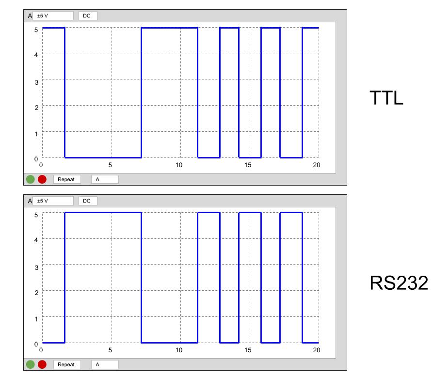
TTL
Between VCC and 0. Sends serial data. True TTL data - Starts at the high voltage
RS232
Inverted TTL data. 0 - VCC *True RS232 should order TTL and purchase an inverter
USB
Connect sensor through USB to a logic device and read through a serial terminal.
I2C - Inter Integrated Circuit
Most complicated to work with. I2C includes 2 lines: One line is for the time, the other for the data.
4. Calibrated Beam Patterns
We’ve referenced our calibrated beam patterns in the article MaxBotix Fully Calibrated Beam Patterns.To summarize that article:Our sensor beam patterns are factory calibrated for many applications. Each sensor line/model reflects different sensitivities and detection zones.There is little to no deviation between our sensors of the same model.Benefits:
Consistent performance
Reliability
In Conclusion
We created this resource to help our audience to easily identify and differentiate the sensors we offer.
If you have any questions, concerns, or need assistance with sensor selection, contact our team at techsupport@maxbotix.com


 At a glance, you can see it is a weather-resistant sensor, with self-cleaning, long-range and high sensitivity. Ideally, a sensor with these specs is ideal for tank and bin level measurement.
*Read more about the MB7563.
At a glance, you can see it is a weather-resistant sensor, with self-cleaning, long-range and high sensitivity. Ideally, a sensor with these specs is ideal for tank and bin level measurement.
*Read more about the MB7563.
 Analog voltage

 TTL
TTL
 USB
USB
