
External Noise Interference

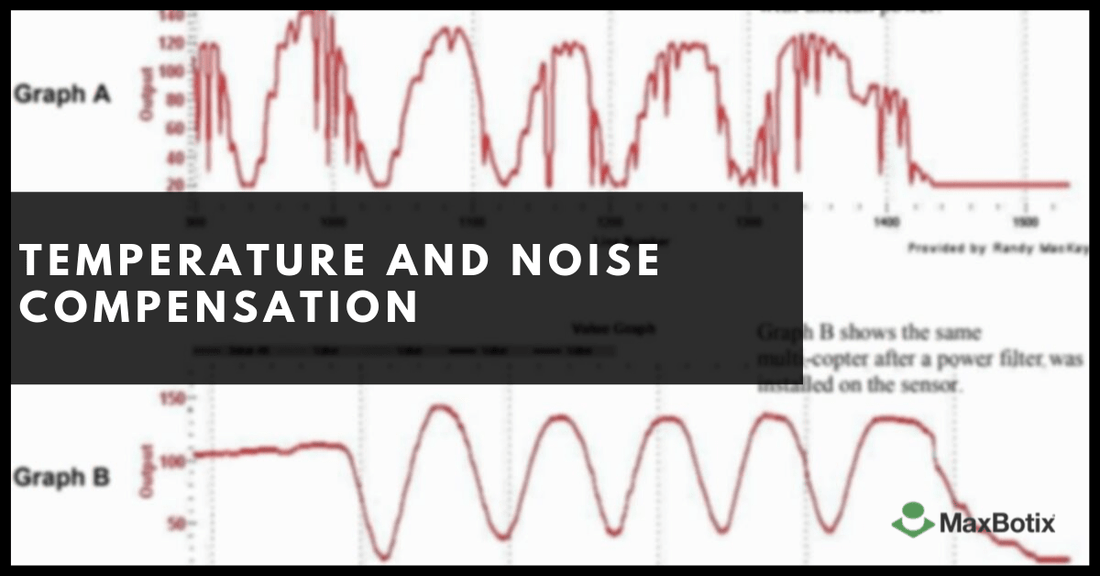
Noise interference can affect UAVs, robots in industrial applications, and other automation solutions. Sensor noise in these environments can be a significant challenge. In this section, we can give you some insight on how to mitigate these (potential) issues. Power supply lines, as well as other EMI (electromagnetic interference) sources, can affect the performance of the sensor. The most common culprit is electrical generators or motors. If this is the case, shielded cables should be used for the best protection. Additionally, the sensors are very sensitive to supply voltage and would need clean stable power for the best performance. For that, we suggest using a Power Supply Filter, also referred to as MB7961. The MB7961 helps stabilize range data and clean the sensor input power. Mainly used on UAVs multi-copters, robots, and environments with known dirty power or electrical noise. In the graphs below, Graph A displays the readings of unclean power, while Graph B shows the range readings after a power filter was applied.

If this is the case, we have instructions on how to create a power supply filter that would solve this. Please see the following link for more information on the power supply filter: https://www.maxbotix.com/documents/MB7961_Datasheet.pdf
We recommend verifying that regulated power is supplied to the sensor, as well as using shielded cable if any EMI source is present.
Does background noise such as table saws, drills, ventilator fans, etc. inhibit the sensors?
It is possible that the background noise could affect the sensor. Typically, noise from motors or electrical generators causes the most interference. Such noise in sensors can vary based on the proximity of the equipment to the sensor. The sensor is only looking for a specific frequency, 42 kHz, and any other frequency outside of this would have minimal effect.

To eliminate the possibility of electrical/acoustic noise, we have a quick test for you to perform. If you received stable readings on a table, you could test the sensor in your original mount with something directly in front of the transducer. This should force the sensor to report minimum range or close to it, and you should see stable readings within a few millimeters.
Temperature Compensation
What exactly do we mean by "temperature compensation"? The sensor will compensate for the ambient air temperature and apply this to the range readings for higher accuracy. Understanding how do temperature affects sensors is crucial for achieving precise readings. The speed-of-sound in the air increases about 0.6 meters per second, per degree centigrade. For example, the MB1033 sensor measures the temperature and compensates the range readings for changes in the speed-of-sound based on temperature. The operation temperatures of our sensors are -40°C to +65°C. The self heating (15mW at 5V, or 8mW at 3.3V) will change the temperature of the sensor by about 1 degree C. The amount of self heating is dependent upon user mounting. Most importantly, the actual air temperature of the path between the sensor and the target may not match the temperature measured at the sensor electronics. Sensors mounted in vertical applications, or applications where the environmental temperature gradient is severe, may experience a large temperature measurement error which will affect the sensor accuracy. For example, buildings with a height of 2-meters can have floor to ceiling temperature variations of 5°C or more. Because of these temperature effects, users desiring the highest accuracy output are encouraged to use a properly mounted external temperature sensor or to manually account for this measurement error. Temperature Compensation that uses the time of flight in seconds, the temperature in degrees centigrade, and yields the distance in meters works for all of our products. Dm = TOF *((20.05*SQRT(Tc+273.15))/2) Where TOF - the measured Time Of Flight in seconds, Tc - the ambient temperature in degrees C, SQRT - the symbol* for square root (* in Microsoft Excel) and Dm - the distance in meters. For 23 degrees C and 0.0058 seconds (or 5.8mS) the distance calculates to 1.0006 meter. If using the serial output, first convert the distance reported by the sensor to TOF by using 147uS per inch (TOF = inches * 1.47E-4) or 58uS per cm (TOF = cm * 5.8E-5) and then insert the TOF into the above formula. Review our Temperature Compensation document with more detailed information.
https://maxbotix.com/blogs/blog/noise-temperature-sensor-operation?_pos=3&_sid=fdfed3407&_ss=r
Our Sensor Lines with Temperature Compensation and Applications Used Most
Our HRLV, HRXL, and SCXL lines of sensors all have temperature compensation. Compensating for temperature is ideal mainly for outdoor (non-protected) applications.
HRLV-MaxSonar-EZ Product Line
HRLV-MaxSonar-EZ ultrasonic rangefinders offer 1mm resolution, 2.5-5.5VDC operation, temperature compensation, automatic calibration, high accuracy, and stable operation in multi-sensor environments. The output options for this ultrasonic sensor line are pulse-width, analog voltage, and a choice of asynchronous RS232 or TTL serial.
Buy Now
HRXL‑MaxSonar‑WRS Product Line
The IP67 rated HRXL-MaxSonar-WRS ultrasonic rangefinders provide reliable snow depth readings, 1mm resolution, 2.5-5.5VDC operation, a narrow beam pattern, high power output, noise rejection, automatic calibration, and temperature compensation. The output options for this ultrasonic sensor line are pulse-width, analog voltage, and a choice of asynchronous RS232 or TTL serial.
Buy Now SCXL‑MaxSonar‑WRS Product Line
This IP67 rated SCXL-MaxSonar-WRS line reduces the impact of condensation and frost when ran continuously in closed or high-moisture environments. These ultrasonic rangefinders offer reliable snow depth readings, 1mm resolution, 2.5-5.5VDC operation, a narrow beam pattern, high power output, noise rejection, automatic calibration, and temperature compensation.
Buy Now