Key Takeaways
- Capture the analog envelope
- Use a picoscope
- Screen shot the analog envelope
The analog envelope output is the log compressed voltage output of the acoustic return signal, which provides users with the ability to see the internal workings of the sensor. This output allows users the ability to easily verify the overall operation of their system application. Advanced users may chose to read the analog envelope and process the data with their own digital converter. This output can also provide Maxbotix Inc., with the data needed to assist with troubleshooting or to provide a semi-custom firmware solution for an application.
Troubleshooting with the Analog Envelope
The most common example of using the analog envelope is to capture interference sources, such as physical objects cluttering the acoustic path to the target. Another example of use is to see if there is another acoustic noise source nearby.
Setup Instructions
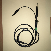
A Picoscope is a USB connected software oscilloscope displays electrical signals as they change over time, which works great for reading the analog envelope.
- Connect sensor ground, and V+ to a power supply set at 5V.
- Using probe from Picoscope, connect the main clip lead of probe to pin 2 for the analog envelope output.
- Connect the small clip lead from probe to the ground pin 7 of the sensor.
- Open the picoscope software on your computer.
How to capture the analog envelope
1) The transmit burst is the highest amplitude signal and should be used to trigger the Picoscope. Set the scope to trigger/sync on the transmit burst which is typically ~2.9V with a 5V input. (Although auto triggering is normally used for waveform setup, to capture a waveform, the triggering should be set to “Normal” or “Repeat” to assure the trigger occurs at the correct location on the waveform.)

Figure 3. Transmit Burst
Figure 4. Trigger Controls
2) Set the vertical control to maximize the transmit burst, target, and clutter information. When powered with 3V to 5V you can typically use 1mS per division to capture the waveform data.

Figure 5. Voltage and Division Settings
3) Set the horizontal controls to capture all of the information of interest. At room temperature the speed of sound is 58uS per cm, so if you need to capture objects out to 1 meter, then (100cm * 58uS) you must capture data for 580uS or 5.8mS. This corresponds to setting the horizontal control to 1mS per division and will allow data capture to 10mS on most oscilloscopes and should work for up-close measurements of less than 1.5 meters. For longer measurements, typically a 10mS per division will suffice.

Figure 6. Picoscope Settings
4) Now you can capture a clear screenshot of the analog envelope output. Label your screenshot with the settings you used.

Figure 7. Analog Envelope Screenshot
For users who need custom firmware matched to their application, this output can provide MaxBotix Inc., with the data to help aid in the design of the firmware needed. In bin measurements the analog envelope can be used to capture the output data for the bin level. A user can capture the analog envelope when the bin is empty (0%), 10%, 20% etc., up to 100% full. These images then provide MaxBotix with the data required to match the firmware to the given application and incorporate the needed margins for robust operation.
Compatible Part Numbers
The following list of part numbers have the Analog Envelope output available: MB13XX MB707X MB7092
Synopsis
The analog envelope can be a valuable output when wanting to range multiple targets, or when in an area with noise issues. Using a picoscope or an oscilloscope will be a useful tool to display the observed waveform information, and a good screenshot of the analog envelope can be used for troubleshooting on your own or sent to our technical support staff to help us trouble shoot the problem for you.
Contact our technical support team if you need any additional help or have any questions about using the Analog Envelope or other sensor outputs used by our sensors. We are here to help you succeed.


