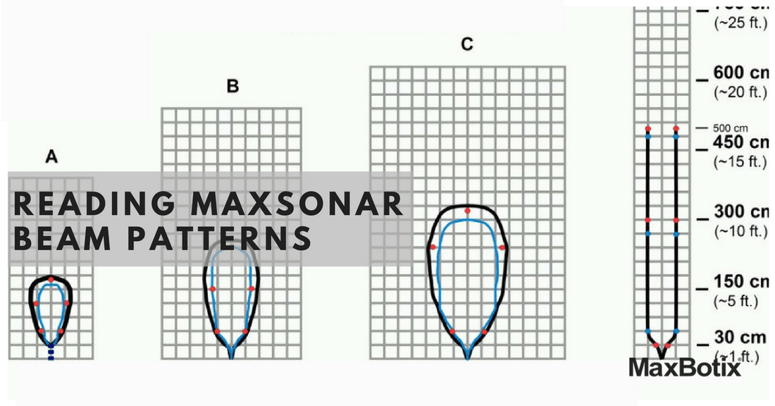
MaxBotix Inc. provides beam patterns for all of our ultrasonic sensors to assist users in choosing the correct sensor for their application, target size, and distance. Each beam pattern diagram is a 2D representation of the detection area of the sensor. In reality, the actual beam pattern is shaped like a 3D cone (having the same detection pattern both vertically and horizontally). We hope that our work in creating and explaining our beam patterns will contribute to better ultrasonic sensor selection. If you still need assistance with our beam patterns, please reach out to us at techsupport@maxbotix.com.
Things to know before reading MaxSonar Beam Patterns:
- The beam patterns are provided as approximations. Our sensors are factory calibrated, and the beam patterns are accurate for each sensor. That being said, there still may be slight differences in sensors with the same part number.
- We test our sensors with dowels, which are essentially vertically hanging pegs/poles. The dowels provide consistent characteristics for every test. This allows easy comparison of one MaxSonar sensor to another. The smaller the dowel or target, the smaller the beam pattern.
- You read our beam patterns by looking at the target size and distance of detection. Our smallest target and distance will always be our first diagram (labeled letter “A”) in the figure. Our largest target and distance is always our last diagram.
- You do not select a beam pattern for a sensor. To select a beam pattern appropriate for your application, find a sensor that matches what you need.

Understanding Voltage
When you increase the voltage, the sensor emits more sound. This typically means that the higher the voltage, the larger the ultrasonic sensor beam angle. And as the voltage to the sensor reduces, the size of the beam pattern normally decreases. On our plotted beam patterns, a supplied power of 5 volts is the black line, 3.3 volts are red dots, and 2.7 volts is the blue line. In Beam Pattern A, you can see how the patterns change with voltage changes.
Target Size
Target size is a big factor in beam readings. Larger targets reflect more sound. This means they can be at a further distance while still being detected by the sensor (see Beam Pattern D). This narrows the ultrasonic sensor beam angle. Small targets reflect less sound and therefore need to be closer for the sound to return back to the sensor (see Beam Pattern C). This is where voltage comes into play. More voltage means that more sound will hit the target and bounce back to the sensor. This is ideal for smaller targets, as there is a better chance of the sensor receiving the sound waves from the target. As you can see in Beam Pattern D, voltage makes less of an impact on larger targets because the objects already reflect a large amount of sound.


